Unbricking a Buffalo WHR-HP-G300N
Last week I attended the first Freifunk meeting in my hometown. The decision was made to participate to FFBsee with my old Buffalo WHR-HP-G300N router.
Before flashing the latest Freifunk firmware I tried to install a vanilla OpenWrt image for this router. But the outdated DD-WRT image on this router refused to get updated.
After several retries I gave up on the suggested tftp method. I tried several combinations of MAC-Addresses and interfaces always without success. Luckily Kevin Cave on Scarygliders pointed out that the U-Boot on the router can be interrupted with CTRL-C when it tries to request a firmware by tftp.
He also pointed out that the OpenWrt image is prefixed with some 0x20 byte header. So I tweaked the U-Boot environment a bit so I could skip to alter the firmware.
1 2 3 4 5 6 7 | |
There are some interesting environment variables related to firmware update
1 2 3 4 5 6 | |
After setting up a TFTP server and changing your host system to the IPv4 address off 192.168.11.2 You can download a firmware image right from the U-BOOT command prompt:
1 2 3 4 5 6 7 8 9 10 11 12 13 14 15 16 17 | |
So let’s check if the image also suffer from this 0x20 bytes offset
1 2 3 4 5 | |
Of course it is as-well padded by this 0x20 byte offset. Just out of curiosity
1 2 3 4 5 6 7 8 9 10 11 12 13 14 15 16 17 | |
In the line starting with 80f00020 we can see the magic 27051956 ,the expected uImage header, which Kevin Cave on Scarygliders pointed out. So let’s skip this header
1
| |
Please do not save the environment after this modification otherwise your router will may not work properly after this. This is just a temporary modification!
After this modification the test should past fine
1 2 3 4 5 6 7 8 9 10 11 | |
Bingo! This looks promising. We now have to erase the flash and copy the image to it’s new place.
1 2 3 4 5 6 7 8 9 | |
Now it is time to check if everything went fine or if we have created something for the dust bin.
1 2 3 4 5 6 7 8 9 10 11 12 13 14 15 16 17 18 19 20 21 22 23 24 25 26 27 28 29 30 31 32 33 34 35 36 37 38 39 40 41 42 43 44 45 | |
This looks like full success to me. Next step will be increasing the flash size to 8 MB to provide enough space for the FFBsee firmware.
Activating USB_OTG Composite Ethernet + Serial Gadget Support in Yocto’s Poky for UDOO Neo
After playing with UDOOBuntu and the nice USB OTG Gadget support my decision was to provide something similar for my Yocot Port as-well. It turned out that the serial Gadget support was pretty easy the Ethernet support is more complex.
For serial console over the USB OTG port of your NEO you have to change the udooneo.conf file in the folder conf\machine of meta-fsl-arm-extra
MACHINE_FEATURES += " usbgadget usbhost"
SERIAL_CONSOLES ?= "115200;ttymxc0 115200;ttyGS0"

KERNEL_MODULE_AUTOLOAD += " g_serial"
This adds usbgadget support and automatically loads the module g_serial on startup. The line SERIAL_CONSOLES automatically spawns a getty on /dev/ttyGS0 through the inittab.
Due to the fact that only one USB OTG gagdget module can be loaded there are some composite modules available. A combination of serial and Ethernet for example is the g_cdc. To use g_cdc instead of g_serial is pretty simple just change the line
KERNEL_MODULE_AUTOLOAD += " g_serial"
To this
KERNEL_MODULE_AUTOLOAD += " g_cdc"
This will automatically provide serial support and spawns a usb0 network device device on the target and the host. But my Ubuntu host was not able to set get an IP-Adress for this interface. Setting one by hand resolved this. But this is not comparable to the out of the box experience UDOOBuntu provides.
On your host computer you’ll see something like this in your dmesg log
[ 9515.050081] usb 4-1.4.1.1: new high-speed USB device number 12 using ehci-pci
[ 9515.144407] usb 4-1.4.1.1: New USB device found, idVendor=0525, idProduct=a4aa
[ 9515.144411] usb 4-1.4.1.1: New USB device strings: Mfr=1, Product=2, SerialNumber=0
[ 9515.144412] usb 4-1.4.1.1: Product: CDC Composite Gadget
[ 9515.144414] usb 4-1.4.1.1: Manufacturer: Linux 3.14.28_1.0.0_ga-udooboard+g580e305 with 2184000.usb
[ 9515.152930] cdc_ether 4-1.4.1.1:1.0 usb0: register 'cdc_ether' at usb-0000:00:1d.0-1.4.1.1, CDC Ethernet Device, 76:26:58:xx:xx:xx
[ 9515.153714] cdc_acm 4-1.4.1.1:1.2: ttyACM0: USB ACM device
[ 9515.176120] cdc_ether 4-1.4.1.1:1.0 usb0: kevent 12 may have been dropped
[ 9515.193036] IPv6: ADDRCONF(NETDEV_UP): usb0: link is not ready
[ 9515.377616] userif-3: sent link down event.
[ 9515.377619] userif-3: sent link up event.
For serial console access you can connet to the UDOO Neo by attaching minicom to /dev/ttyACM0 at 115200 Baud 8N1 No flow control, or any other treminal emulator of your choice.
Attaching a Serial Console to UDOO Neo
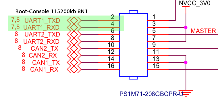
Yesterday my long time awaited UDOO Neo board has arrived. They do provide a really good getting started guide for UDOO Neo. But for my Yocto Port I need access to the serial console to check the output of the U-Boot and the kernel. So I’ve checked the UDOO Neo Schematics and located UART1 on the connector J7.
It is so incredible that they do provide the schematics. It is much easier to check the PINOUT. To connect the UDOO to a terminal client you need the following stuff
- 1 x USB to serial converter with 3.3V output. Do not use any 5V type, this may damage your UDOO Neo! I use some cheap Chinese CH341 USB to UART converters. They cost about 3€ but are not FTDI clones.
- 3 Jumper wires. It depends on your USB to serial converter if you need male <-> male or female <-> male. I needed female <-> male connectors
- 1 x UDOO Neo board
- 1 x Powersupply for the Neo.
- 1 x Micro SD-Card with the UDOOBuntu or a Yocto build for UDOO Neo
For power connection and flashing the SD-Card please have a look at the getting started guide for UDOO Neo.
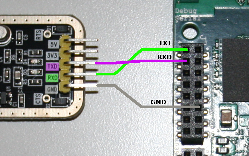
Before you plug-in the serial wires you have to remove any power source from the UDOO board. Otherwise you may damage your board. Double check if your adapter is a 3.3V. Connect the ground line (GND) of your USB to serial converter with the PIN 11 of the J7 connector. Then you have to connect the RX and TX PINs. But remember you have to cross them. Why do we need to cross RX and TX?
This is because TX is transmit and if the UDOO Board and your PC are transmitting on the same line nothing is received on both sides. So you have to connect the RX PIN of the UDOO board, PIN 4 of J7, with the TX PIN of your converter. The TX, PIN 2 of J7, from UDOO is connected to the RX PIN of converter.
After this you can check their tutorial how to fire up an Terminal Emulator on your Platform of choice and connect to the NEO at the following settings:
- 115200 kB
- 8N1
- No Flow-Control
I do prefer minicom under Linux for this job.
UDOO Neo direct USB console
You may have noticed while booting the official UDOOBuntu image image a new disk is suddenly mounted on your PC. And you have a new network interface connected as well. Last but not least even a new serial interface is available.
[...]
[ 4885.463264] cdc_acm 4-1.4.1.1:1.2: ttyACM0: USB ACM device
[ 4885.463682] usbcore: registered new interface driver cdc_acm
[ 4885.463685] cdc_acm: USB Abstract Control Model driver for USB modems and ISDN adapters
[...]
You can use minicom with /dev/ttyACM0 and the same settings like above.
Ubuntu 14.04.3 LTS udooneo ttyGS0


default username:password is [udooer:udooer]
udooneo login:
This is absolutely awesome!
Tweaking Freescales Yocto Community BSP Builds
Maurice le Rutte asked me on Twitter if it is possible to add support for the first UDOO board and building a DirectFB enabled image. After some research it looked like a solution for the DirectFB task should be not that big issue.
I guess you have already a running Yocto environment based on the Freescale BSP comunity layers. To build a DirectFB image some tweaking is needed. You have to add those lines to your conf/local.conf
DISTRO_FEATURES_remove = "x11"
DISTRO_FEATURES_remove = "wayland"
DISTRO_FEATURES_append = " directfb"
The first two lines remove support for wayland and X11 which will conflict with DirectFB and will prevent a successful build. With this modification you can build a DirectFB image. The extra white space in front of directfb is mandatory!
bitbake core-image-directfb
This is the right time to fetch some coffee.
Another tweak I prefer to do in the conf/local.conf is switching from RPM to IPK as package manager. It is more lightweight and a little bit faster than RPM or DEB. You only have to change the variable PACKAGE_CLASSES to package_ipk
PACKAGE_CLASSES ?= "package_ipk"
At the moment I am working on a Machine configuration for the UDOO Quad board
OpenEmbedded Support for the Upcomming UDOO Neo
After beeing part of the Kickstarter campaign for the UDOO NEO board. I am looking forward to play with this little beast.

During the meantime I decided to add the UDOO NEO board to the Freescale OpenEmbedded community layer. Due to the fact my board did not yet arrived I’ve not yet created a patch to ask for integration into the official Freescale OpenEmbedded community layer. This will be done when I’ve tested the layer.
If you are interested in my work you can find my personal fork right here at github. You have to use the fido branch. To keep things simple I’ve created my own branch of the fsl-community-bsp-platform repo repository.
Installing the BSP
To get the BSP you need to have repo installed and use it as:
Install the repo utility:
$: mkdir ~/bin
$: curl http://commondatastorage.googleapis.com/git-repo-downloads/repo > ~/bin/repo
$: chmod a+x ~/bin/repo
Download the BSP source:
$: PATH=${PATH}:~/bin
$: mkdir fsl-community-bsp
$: cd fsl-community-bsp
$: repo init -u https://github.com/graugans/fsl-community-bsp-platform -b fido
$: repo sync
At the end of the commands you have every metadata you need to start work with.
Building the Image
To start a base image build execute the following command on a decent machine and grab some coffee…
$: source ./setup-environment udooneo-build $: bitbake core-image-base
If everything was build fine you’ll find a SD-Card image right here:
tmp/deploy/images/udooneo/core-image-base-udooneo.sdcard
You can write this image directly to any supported SD-Card. Plug it into your freshly unboxed UDOO NEO and hopefully have fun. This image is completly untested and you have to use it on your own risk…
Creating your personal Toolchain
If you want to develop your own software for the UDOO Neo you’ll need some cross toolchain. This can be achieved very easy with the OpenEmbedded universe.
$ bitbake core-image-base -cpopulate_sdk
The resulting self extracting shell script you’ll find right here:
tmp/deploy/sdk/poky-glibc-x86_64-core-image-base-cortexa9hf-vfp-neon-toolchain-1.8.sh
In case of any questions just leave a comment on my Blog.
Installing STM32CubeMX on Linux
The STMicroelectronics STM32CubeMX is delivered as a exe file what implies that it is eintended to run on Windows systems only. But due to the fact it is a JAVA application we can run it on Linux as-well.
Installation
To install the STM32CubeMX administration rights are needed
sudo java -jar /tmp/SetupSTM32CubeMX-4.9.0.exe
Running STM32CubeMX
If you’ve selected the default install location you can run STM32CubeMX like this:
java -jar /usr/local/STMicroelectronics/STM32Cube/STM32CubeMX/STM32CubeMX.exe
[WIP] NIM_DVB-S/S2 V1.0 Pinout
This is a work in progress article and will be updated over time.
| PIN | Side B | Side A |
|---|---|---|
| 1 | GND | n.c. |
| 2 | n.c. | GND |
| 3 | n.c. | n.c. |
| 4 | n.c. | n.c. |
| 5 | n.c. | n.c. |
| 6 | n.c. | GND |
| 7 | n.c. | n.c. |
| 8 | n.c. | GND |
| 9 | n.c. | n.c. |
| 10 | n.c. | n.c. |
| 11 | n.c. | GND |
| – | Key notch | Key notch |
| 12 | GND | GND |
| 13 | n.c. | n.c. |
| 14 | n.c. | n.c. |
| 15 | n.c. | GND |
| 16 | n.c. | n.c. |
| 17 | n.c. | n.c. |
| 18 | GND | GND |
PCI-Express Connectors From China
After my decision to build a full Open Source Software based DVB-S2 USB module I ordered some PCI-Express connectors from China on Aliexpress. The delivery time was quite low I received my package about 11 days after placing my order. This is really quick for standard delivery from China to Germany. Next step will be adding this connector to Eagle PCB Design Software. And designing a small breadboard to PCI-Express board and host it on OSHPark.
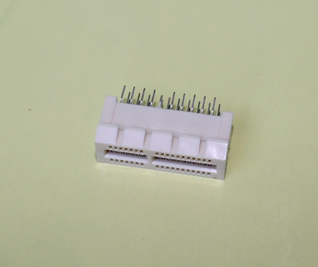
I have not found any data sheet for this connector yet. On one side it has an engraving with ,,tyco/Electronics” and on the other side some code ,,08306ED’‘.
Update
After some research I found a ,,data sheet’‘ ENG_DS_4-1773442-7_0308-2.pdf but it lacks detailed drawings about the PIN pitch. After some research I discovered that those connectors are described in the PCI Express Card Electromechanical Specification.
Full Open Source DVB-S2 Board
Some time ago I thought it would be fun to build a USB DVB-S2 device which runs on 100% OpenSource Software. Due to the fact I do not have any tooling for soldering complex chips I decided to build this project on hardware which is already available. For interconnection of the DVB part with the PC or a Single board computer like the ODROID-C1 or Raspberry PI my decision was to use a Cypress FX2 CY7C68013A evaluation board. You can buy them for under 10€ in far east on ebay. I bought one of the Lcsoft Mini Boards. The coreboot project provides a schematic for the Lcsoft board.

The Cypress FX2 CY7C68013A is based on a 8051 core. Not one of my favorite hacking platform but I’ll give it a try. There is a Open Source Framework for firmware development it is called fxlib. After some research on Google I found the project Termini. The firmware for the Termini hardware is available via the linuxtv.org CVS repository. They provide a specification for the USB communication between the host controller and the FX2. There are already some USB 2.0 USB DVB-S2 devices based on the Cypress FX2 CY7C68013A like the DVBSKY S960.
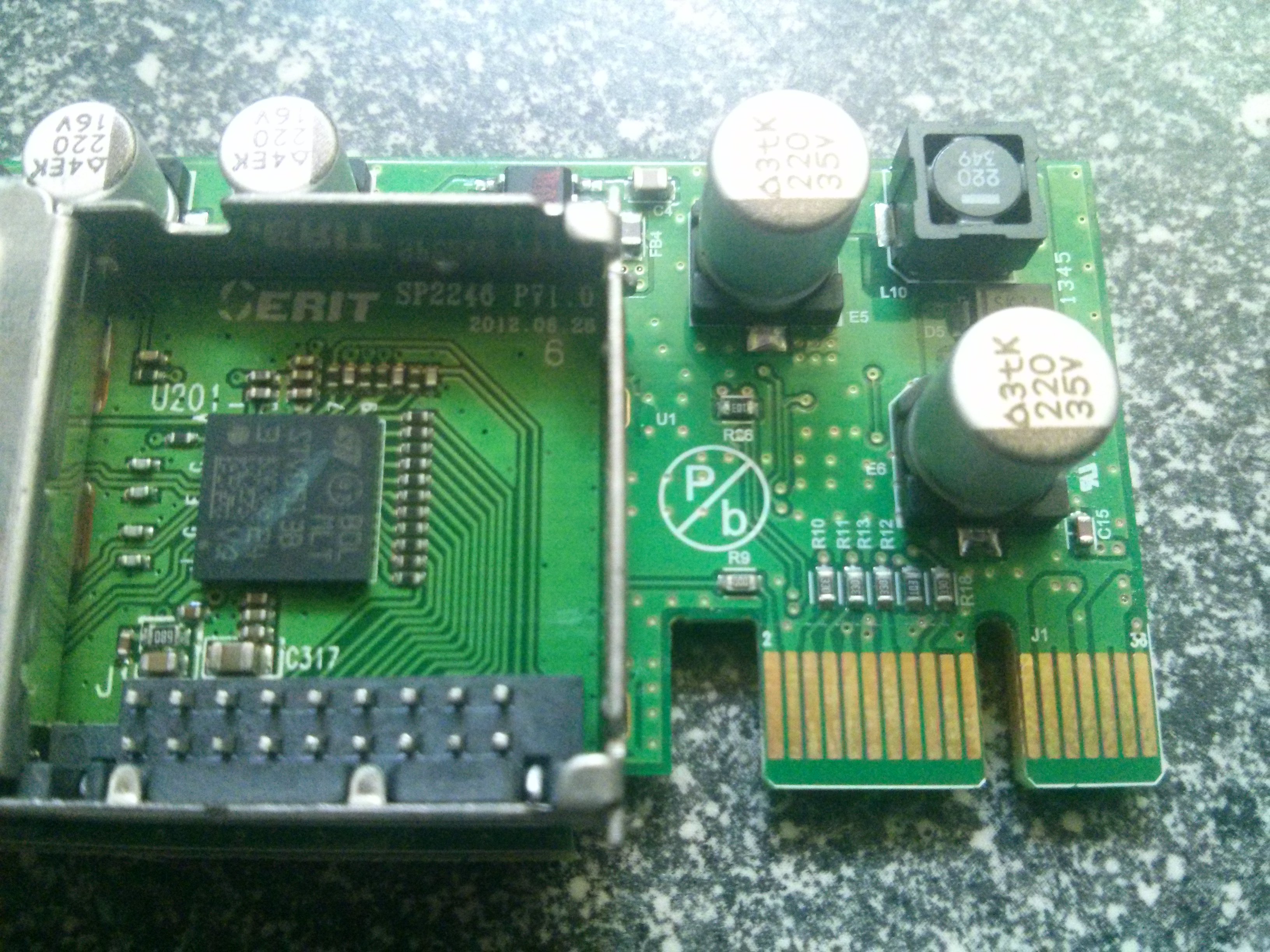
The last part in the jigsaw puzzle is the DVB-S2 tuner and demodulator part. Some of the linux based Set-Top-Boxes provide swappable tuner modules one of them is the manufacturer GigaBlue. They sell a DVB-S2 Tuner based on the Serit SP2246 NIM for DVB-S2. The SP2246 is based on the STV6111 tuner and the STV0913 demodulator. It looks like the tuner module is connected via a PCI-Express x1 36Pin connector. Serit provides a very detailed data sheet so at least a few of the PINs should be easily mappable with a multi meter.
Watterott HDMI/DVI - RGB Adapter EDID Hacks
The German Maker supplier Watterott sells a HDMI/DVI to RGB Display adapter. The Adapter itself contains a ATmega32U4 controller attached to USB, which works as touchcontroller. The designs and firmware for the adapter are available on GitHub. I am not sure if we can call this OpenSource because of a missing License file.
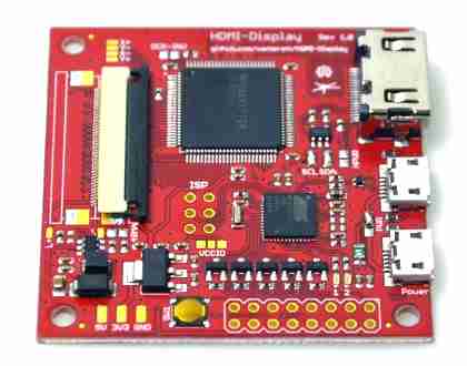
Beside the HDMI/DVI Bridge controller the board contains a EEPREOM to store the EDID data. EDID is needed to provide the attached Host device like your PC or Mac to identify what resolution and capabilities your Display has.
Due to the fact that the adapter supports a wide range of displays the EEPROM is not programmed on a freshly ordered board.
Flashing the EDID EEPROM
Watterott suggests to flash the EEPROM through the ATmega32U4 controller and provides a short description how to do this. But this requires to close two solder jumpers. I decided to flash the EDID EEPROM with my Bus Pirate and the Delock 65168
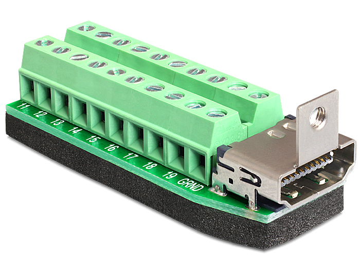
For me the Delock 65168 is the perfect toy to play around with EDID or HDMI CEC.
The host controller communicates through I2C with the EDID EEPROM. There are at least 3 line needed to establish the I2C communication. You need a good ground connection (GND) and a clock line (SCL) and of course the data line (SDA)