ODROID-C1 Enabling Bootlogo on Yocto Builds
The U-Boot for the Amlogic S805 from Hardkernel has the capabilities to display a bootlogo. It is not that easy to find any bootlogo that complies to a licence which can be used in comercial and in open source environments. Using the yocto logo is most probably prohibited, so I decided to design my own logo. And saved it to 24-bit Windows BMP image with the dimension of 1280×720 as statet in the ODROID-C1 Wiki

Modifying boot.ini
In my Amlogic meta layer for the yocto build system I do not use a Fat32 boot partition so the original bootlogo loading command needed some minor modifications. The bootlogo is name bootlogo.bmp and should be copied to /boot.
# loading and displaying bootlogo
logo size ${outputmode}
video open
video clear
video dev open ${outputmode}
ext4load mmc 0:1 ${loadaddr_logo} /boot/bootlogo.bmp
bmp display ${loadaddr_logo}
bmp scale
You can either add this to your boot.ini or wait until I pushed a patch for meta-amlogic.
Modifying the U-Boot environment
Another option is to change the U-Boot environment. There is already a variable called preloadlogo. We can update the command to load the bootlogo from ext4 instead of Fat32
setenv preloadlogo 'logo size ${outputmode};video open;video clear;video dev open ${outputmode};ext4load mmc 0:1 ${loadaddr_logo} /boot/bootlogo.bmp;bmp display ${loadaddr_logo};bmp scale'
Pleas ensure, that you paste this as a single line.
Using H/W Randaom Generator on ODROD-C1 With Yocto
The Amlogic S805 CPU used in the ODROID-C1 contains a hardware random number generator which can be used to increase entropy in the linux kernel. The guys at Hardkernel wrote a tutorial how to enable this in Ubuntu.
Due to the fact that there is a rng-tools recipe in the meta-openembedded repo I thought it would be a no-brainer to get this working in Yocto fido.
Before you can build the rng-tools you need the meta-openembedded meta-oe layer in your bblayer configuration file this may look like this
1 2 3 4 5 6 7 8 9 10 11 | |
After adding the meta-oe layer and preparing the bitbake environment we can build the rng-tools recipe
$ source poky/oe-init-build-env build/
$ bitbake rng-tools
The resulting file can be transfered to the target and installed with the defined package manger. In my case I do use opkg. Please ensure you are using a image with a package manager enabled. I do use core-image-base and add the following to conf/local.conf:
1 2 3 4 5 6 7 8 9 10 11 12 13 14 15 16 | |
Let’s transfer the resulting files to the target.
$ find tmp/deploy/ipk/ -name "rng-tools*"
$ scp tmp/deploy/ipk/cortexa5hf-vfp-neon/rng-tools_4-r0_cortexa5hf-vfp-neon.ipk root@odroidc1:/tmp
Attention: At the moment the recipe for the rng-tools packages installs it’s configuration to /etc/rng-tools but the initscript expects it at /etc/default/rng-tools. I send a patch to the meta-openembedded mailinglist to correct this. The current behaviour of the rng-tools should be pretty okay due to the fact that given no “-r” option the default behavior is to use /dev/hwrng.
Benchmarks
The rng-tools provide some statistical tests for checking if the hardware random generator works as expected.
Without rngd
This runs the FIPS 140-2 tests against the device /dev/random without running rngd
root@odroidc1:~# time rngtest -c1 < /dev/random
rngtest 4
Copyright (c) 2004 by Henrique de Moraes Holschuh
This is free software; see the source for copying conditions.  There is NO warranty; not even for MERCHANTABILITY or FITNESS FOR A PARTICULAR PURPOSE.

rngtest: starting FIPS tests...
rngtest: bits received from input: 20032
rngtest: FIPS 140-2 successes: 1
rngtest: FIPS 140-2 failures: 0
rngtest: FIPS 140-2(2001-10-10) Monobit: 0
rngtest: FIPS 140-2(2001-10-10) Poker: 0
rngtest: FIPS 140-2(2001-10-10) Runs: 0
rngtest: FIPS 140-2(2001-10-10) Long run: 0
rngtest: FIPS 140-2(2001-10-10) Continuous run: 0
rngtest: input channel speed: (min=132.975; avg=132.975; max=132.975)bits/s
rngtest: FIPS tests speed: (min=55.934; avg=55.934; max=55.934)Mibits/s
rngtest: Program run time: 150404986 microseconds
real    2m 30.40s
user    0m 0.00s
sys     0m 0.01s
The average of 132.975 bits/s throughput is pretty low.
With rngd
This runs the FIPS 140-2 tests against the device /dev/random with running rngd
root@odroidc1:~# /etc/init.d/rng-tools start
root@odroidc1:~# time rngtest -c1 < /dev/random
root@odroidc1:~# time rngtest -c100 < /dev/random
rngtest 4
Copyright (c) 2004 by Henrique de Moraes Holschuh
This is free software; see the source for copying conditions.  There is NO warranty; not even for MERCHANTABILITY or FITNESS FOR A PARTICULAR PURPOSE.

rngtest: starting FIPS tests...
rngtest: bits received from input: 2000032
rngtest: FIPS 140-2 successes: 99
rngtest: FIPS 140-2 failures: 1
rngtest: FIPS 140-2(2001-10-10) Monobit: 1
rngtest: FIPS 140-2(2001-10-10) Poker: 0
rngtest: FIPS 140-2(2001-10-10) Runs: 0
rngtest: FIPS 140-2(2001-10-10) Long run: 0
rngtest: FIPS 140-2(2001-10-10) Continuous run: 0
rngtest: input channel speed: (min=5.034; avg=5.310; max=5.374)Mibits/s
rngtest: FIPS tests speed: (min=53.880; avg=58.279; max=58.688)Mibits/s
rngtest: Program run time: 392465 microseconds
Command exited with non-zero status 1
real    0m 0.39s
user    0m 0.03s
sys     0m 0.36s
Now we have an average throughput of 5.310 Mibits/s compared to the 132.975 bits/s without rngd.
Considerations
You might keep in mind that using a hardware random generator may cause security issues. To have a more detailed view on this read this posting and comments on Theodore Ts’o posting on G+. From this posting If I were the NSA, and I wanted to gimmick an RNG, whether it be the one inside the Intel chip or the Android build, it would be a counter encrypted by an AES key known by the NSA. (Why AES? Because RDRAND is documented as using AES in its final whitening stage; so someone taking a quick look at the RDRAND implementation would be expecting AES).
Using the SEGGER J-Link to Access the TI CC2650 Chip
Before you get started install the newest host tools for your SEGGER in my case I installed the Debian package of version V4.98b. On first start the JLinExe installs the apropriate Firmware.
$ JLinkExe -if jtag -device CC2650F128
SEGGER J-Link Commander V4.98b ('?' for help)
Compiled Apr 10 2015 20:27:38
Updating firmware:  J-Link V9 compiled Apr 10 2015 10:51:08
Replacing firmware: J-Link V9 compiled Feb 13 2015 20:37:28
Waiting for new firmware to boot
New firmware booted successfully
On the SimpleLink™ Bluetooth Smart®/Multi-Standard SensorTag they use the CC2650 with 128kB of Flash ROM. So you have to select -device CC2650F128 when running JLinkExe At the moment it seems the CC2650 only supports JTAG debugging and not the more common SWI debug like STM32 do use. Anyway The Segger can run both modes.
After a succesful firmawre update the communication looks like this
SEGGER J-Link Commander V4.98b ('?' for help)
Compiled Apr 10 2015 20:27:38
Info: Device "CC2650F128" selected.
DLL version V4.98b, compiled Apr 10 2015 20:27:35
Firmware: J-Link V9 compiled Apr 10 2015 10:51:08
Hardware: V9.30
S/N: XXXXXXXX
OEM: SEGGER-EDU
Feature(s): FlashBP, GDB
VTarget = 2.800V
Info: TotalIRLen = 10, IRPrint = 0x0011
Info: Found Cortex-M3 r2p1, Little endian.
Info: FPUnit: 6 code (BP) slots and 2 literal slots
Info: CoreSight components:
Info: ROMTbl 0 @ E00FF000
Info: ROMTbl 0 [0]: FFF0F000, CID: B105E00D, PID: 000BB000 SCS
Info: ROMTbl 0 [1]: FFF02000, CID: B105E00D, PID: 003BB002 DWT
Info: ROMTbl 0 [2]: FFF03000, CID: B105E00D, PID: 002BB003 FPB
Info: ROMTbl 0 [3]: FFF01000, CID: B105E00D, PID: 003BB001 ITM
Info: ROMTbl 0 [4]: FFF41000, CID: B105900D, PID: 003BB923 TPIU-Lite
Found 2 JTAG devices, Total IRLen = 10:
 #0 Id: 0x4BA00477, IRLen: 04, IRPrint: 0x1, CoreSight JTAG-DP (ARM)
 #1 Id: 0x8B99A02F, IRLen: 06, IRPrint: 0x1, TI ICEPick
Cortex-M3 identified.
Target interface speed: 100 kHz
J-Link>
The next step is to create a firmware backup of the original firmware. This is needed because this little beast at the momemnt denies to build its firmware under Linux. The CodeComposerStudio Projekt is using some Windows Tools to build and expects a specific directory layout.
ORICO BTA-402 USB Bluetooth 4.0 Low Energy Micro Adapter on ODROID-C1
Today I had some fun with Bluetooth Low Energy and my ODROID C1 In an earlier Blog Post I described how to enable Bluetooth Low Energy Support in Yocto.
Recently I bought this ORICO BTA-402 USB Bluetooth 4.0 Low Energy Micro Adapter on Amazon to play with Bluetooth Low Energy. The USB Dongle was automatically detected by my meta-amlogic’s kernel configuration for the ODROID C1
I used the New SimpleLink™ Bluetooth Smart®/Multi-Standard SensorTag as the device to connect to.
On the ODROID-C1 device run the following commands:
root@odroidc1:~# hciconfig
hci0:   Type: BR/EDR  Bus: USB
    BD Address: 00:1A:7D:DA:71:09  ACL MTU: 310:10  SCO MTU: 64:8
    DOWN
    RX bytes:547 acl:0 sco:0 events:27 errors:0
    TX bytes:384 acl:0 sco:0 commands:27 errors:0
Check if your adapter is DOWN as you can see in the example above. If the adapter is down you have to bring it up befare any other action can take place
hciconfig device up
After this you can re-check if your adapter is UP and RUNNING
root@odroidc1:~# hciconfig
hci0:   Type: BR/EDR  Bus: USB
        BD Address: 00:1A:7D:DA:71:09  ACL MTU: 310:10  SCO MTU: 64:8
        UP RUNNING
        RX bytes:10116 acl:72 sco:0 events:364 errors:0
        TX bytes:1858 acl:73 sco:0 commands:66 errors:0
Now you can scan for Bluetooth Low Energy devices Please ensure that your SensorTag is in Advertise Mode. Whith the default Firmware this can be achieved by pressing the Power Button.
root@odroidc1:~# hcitool lescan
LE Scan ...
50:C4:7F:6C:18:2C (unknown)
50:C4:7F:6C:18:2C (unknown)
50:C4:7F:6C:18:2C (unknown)
50:C4:7F:6C:18:2C (unknown)
50:C4:7F:6C:18:2C (unknown)
68:C9:0B:06:EF:0B (unknown)
68:C9:0B:06:EF:0B CC2650 SensorTag
68:C9:0B:06:EF:0B (unknown)
68:C9:0B:06:EF:0B CC2650 SensorTag
68:C9:0B:06:EF:0B (unknown)
68:C9:0B:06:EF:0B CC2650 SensorTag
68:C9:0B:06:EF:0B (unknown)
68:C9:0B:06:EF:0B CC2650 SensorTag
50:C4:7F:6C:18:2C (unknown)
After a successful scan we can query some information from the SensorTag
root@odroidc1:~# hcitool leinfo 68:C9:0B:06:EF:0B
Requesting information ...
        Handle: 71 (0x0047)
        LMP Version: 4.1 (0x7) LMP Subversion: 0x200
        Manufacturer: Texas Instruments Inc. (13)
        Features: 0x01 0x00 0x00 0x00 0x00 0x00 0x00 0x00
Now lets connect to the SensorTag
root@odroidc1:~# hcitool lecc 68:C9:0B:06:EF:0B
Connection handle 71
After this we can use the gatttool from the BlueZ5 package to connect to the GATT Server on the SensorTag
root@odroidc1:~# gatttool -b 68:C9:0B:06:EF:0B --interactive
[68:C9:0B:06:EF:0B][LE]>
Establish a connection to the GATT Server
 [68:C9:0B:06:EF:0B][LE]> connect
 Attempting to connect to 68:C9:0B:06:EF:0B
 Connection successful
Scan for Primary UUIDs
[68:C9:0B:06:EF:0B][LE]> primary
attr handle: 0x0001, end grp handle: 0x0007 uuid: 00001800-0000-1000-8000-00805f9b34fb
attr handle: 0x0008, end grp handle: 0x000b uuid: 00001801-0000-1000-8000-00805f9b34fb
attr handle: 0x000c, end grp handle: 0x001e uuid: 0000180a-0000-1000-8000-00805f9b34fb
attr handle: 0x001f, end grp handle: 0x0026 uuid: f000aa00-0451-4000-b000-000000000000
attr handle: 0x0027, end grp handle: 0x002e uuid: f000aa20-0451-4000-b000-000000000000
attr handle: 0x002f, end grp handle: 0x0036 uuid: f000aa40-0451-4000-b000-000000000000
attr handle: 0x0037, end grp handle: 0x003e uuid: f000aa80-0451-4000-b000-000000000000
attr handle: 0x003f, end grp handle: 0x0046 uuid: f000aa70-0451-4000-b000-000000000000
attr handle: 0x0047, end grp handle: 0x004b uuid: 0000ffe0-0000-1000-8000-00805f9b34fb
attr handle: 0x004c, end grp handle: 0x0050 uuid: f000aa64-0451-4000-b000-000000000000
attr handle: 0x0051, end grp handle: 0x0058 uuid: f000ac00-0451-4000-b000-000000000000
attr handle: 0x0059, end grp handle: 0x0060 uuid: f000ccc0-0451-4000-b000-000000000000
attr handle: 0x0061, end grp handle: 0xffff uuid: f000ffc0-0451-4000-b000-000000000000
To receive notifications on Key Press Events send the following to the device
[68:C9:0B:06:EF:0B][LE]> char-write-req 4a 0100
Notification handle = 0x0049 value: 01
Notification handle = 0x0049 value: 00
Notification handle = 0x0049 value: 01
Notification handle = 0x0049 value: 00
Notification handle = 0x0049 value: 01
Notification handle = 0x0049 value: 00
Notification handle = 0x0049 value: 01
Notification handle = 0x0049 value: 00
Now each key press and release should be displayed in the gatttool. Frankly this key press event notification is just copy past from this vine posting.
Running BlueZ5 on Yocto/OpenEmbedded
At the moment yocto/openembedded ships with BlueZ4 as the Linux Bluetooth protocol stack. Due to the fact that Bluetooth low energy is only supported in BlueZ5 this is a bit of a disappointment. There is a long-standing bug report on this #5031 . But since the commit 1139cc4e… the used BlueZ version can be selected. According to the reference manual BlueZ5 can be enabled by adding bluez5 to the DISTRO_FEATURES for me the easiest way to to this was adding the following line to my conf/local.conf in the Build Directory.
DISTRO_FEATURES = "ext2 alsa wifi usbhost bluetooth bluez5 ${DISTRO_FEATURES_LIBC}"
This disables x11 for example. But you may also could add something like this:
DISTRO_FEATURES_append = "bluez5"
After this run an build of your preferred image. In my case this was “core-image-base”
bitbake core-image-base
To have full bluetooth support on the target I needed to install some extra packages. To get a list of all bluetooth related packages run the following command. For this you need a opkg/ipkg feed server.
root@odroidc1:~# opkg list | grep blue
bluez5 - 5.29-r0 - Linux Bluetooth Stack Userland V5  Linux Bluetooth stack V5 userland
bluez5-dbg - 5.29-r0 - Linux Bluetooth Stack Userland V5 - Debugging files  Linux Bluetooth
bluez5-dev - 5.29-r0 - Linux Bluetooth Stack Userland V5 - Development files  Linux Bluetooth
bluez5-doc - 5.29-r0 - Linux Bluetooth Stack Userland V5 - Documentation files  Linux Bluetooth
bluez5-noinst-tools - 5.29-r0 - Linux Bluetooth Stack Userland V5  Linux Bluetooth stack V5 userland
bluez5-obex - 5.29-r0 - Linux Bluetooth Stack Userland V5  Linux Bluetooth stack V5 userland
bluez5-testtools - 5.29-r0 - Linux Bluetooth Stack Userland V5  Linux Bluetooth stack V5 userland
libasound-module-bluez - 5.29-r0 - Linux Bluetooth Stack Userland V5  Linux Bluetooth stack V5 userland
packagegroup-base-bluetooth - 1.0-r83 - Bluetooth support  Merge machine and distro options to create a basic
I installed the following packages:
bluez5-testtools, bluez5-noinst-tools
The later bluez5-noinst-tools was required for the gatttool.
New Blog Based on Octopress
This is my new Blog based on Octopress and Octostrap3
Building a Yocto Image for the A20 OLinuXino LIME
Some time ago I ordered a A20-OLinuXino-LIME-4GB board. This was planed as a replacement for my not so beloved Raspberry PI. I am not that big fan of the PI because of the wacky SD-Card holder and the USB stability. I hope the 4GB NAND of the A20-OLinuXino-LIME-4GB Will improve the stability of my target application.
[Update - 2014-10-01]
I’ve created a successful pull-request to merge my changes into the meta-sunxi repository and succeeded with the current master branch. Maybe I also start a pull request for the daisy branch. Due to the fact that the new yocto release is knocking on the door This is may not needed.
As a big fan of the Yocto Project I decided to run poky on my OLinuXino. Due to the fact that the A20-OLinuXino-LIME-4GB is not yet officially supported by the meta-sunxi layer there are some patches needed. Those patches are located in my fork. The patch set is against the daisy branch
Preparation
Clone the git repositories and switch to the daisy branch.
mkdir /data/src/yocto
cd /data/src/yocto
git clone git://git.yoctoproject.org/poky
git clone https://github.com/cybertux/meta-sunxi.git
cd poky
git checkout -b daisy origin/daisy
cd ../meta-sunxi
git checkout -b daisy origin/olimex-a20-lime
Prepare a warm and cozy environment for the build
cd /data/src/yocto/poky
mkdir -p ../build/a20-lime
source oe-init-build-env ../build/a20-lime
Add the sunxi meta-layer to the build environment
--- a/conf/bblayers.conf
+++ b/conf/bblayers.conf
@@ -9,6 +9,7 @@ BBLAYERS ?= " \
   /data/src/yocto/poky/meta \
   /data/src/yocto/poky/meta-yocto \
   /data/src/yocto/poky/meta-yocto-bsp \
+  /data/src/yocto/meta-sunxi \
   "
 BBLAYERS_NON_REMOVABLE ?= " \
   /data/src/yocto/poky/meta \
Set the correct target machine and tuning parameters
diff --git a/conf/local.conf b/conf/local.conf
index bcb0864..6a793e6 100644
--- a/conf/local.conf
+++ b/conf/local.conf
@@ -55,7 +55,7 @@ PARALLEL_MAKE ?= "-j ${@oe.utils.cpu_count()}"
 #MACHINE ?= "edgerouter"
 #
 # This sets the default machine to be qemux86 if no other machine is selected:
-MACHINE ??= "qemux86"
+MACHINE ??= "olinuxino-a20-lime"

 #
 # Where to place downloads
@@ -125,7 +125,7 @@ DISTRO ?= "poky"
 #  - 'package_rpm' for rpm style packages
 # E.g.: PACKAGE_CLASSES ?= "package_rpm package_deb package_ipk"
 # We default to rpm:
-PACKAGE_CLASSES ?= "package_rpm"
+PACKAGE_CLASSES ?= "package_ipk"

 #
 # SDK/ADT target architecture
@@ -134,7 +134,19 @@ PACKAGE_CLASSES ?= "package_rpm"
 # you can build the SDK packages for architectures other than the machine you are
 # running the build on (i.e. building i686 packages on an x86_64 host).
 # Supported values are i686 and x86_64
-#SDKMACHINE ?= "i686"
+SDKMACHINE ?= "i686"
+
+#
+# The default machine settings are meant to be the lowest common denominator,
+# maximizing generality. Significantly better performance (2x-3x) can be achieved
+# with the following settings:
+#
+# Allwinner A20
+#
+# For Allwinner A20 (Cubieboard2/CubieTruck), the following tuning options are recommended:
+#
+# Enable hardfloat, thumb2 and neon capabilities
+DEFAULTTUNE = "cortexa7hf-neon-vfpv4"

 #
 # Extra image configuration defaults
Building the image
Now the image can be build, lean back and grap some coffee, beer, …
bitbake core-image-base

[...]
Build Configuration:
BB_VERSION        = "1.22.0"
BUILD_SYS         = "x86_64-linux"
NATIVELSBSTRING   = "Ubuntu-12.04"
TARGET_SYS        = "arm-poky-linux-gnueabi"
MACHINE           = "olinuxino-a20-lime"
DISTRO            = "poky"
DISTRO_VERSION    = "1.6.1"
TUNE_FEATURES     = "armv7a vfp neon callconvention-hard vfpv4 cortexa7"
TARGET_FPU        = "vfp-vfpv4-neon"
meta
meta-yocto
meta-yocto-bsp    = "daisy:a4d8015687cf9ddd6ef563e29cf840698f81c099"
meta-sunxi        = "olimex-a20-lime:5bb9da72c24a442eecd827a9b85f903281357815"
[...]
After a successful build all images are located in the folder
/data/src/yocto/build/a20-lime/tmp/deploy/images/olinuxino-a20-lime/
Building the SDK
Sometimes it is handy to have a toolchain apart from the whole yocto/poky environment. So lets build some
bitbake -cpopulate_sdk core-image-base
This will take mostly as long as the image build so again grab some coffee, beer or ….. The result is located here:
/data/src/yocto/build/a20-lime/tmp/deploy/sdk/olinuxino-a20-lime/poky-eglibc-i686-core-image-base-cortexa7hf-vfp-vfpv4-neon-toolchain-1.6.1.sh
Installation of the Toolchain
You may need root access to install in /opt
sudo  tmp/deploy/sdk/poky-eglibc-i686-core-image-base-cortexa7hf-vfp-vfpv4-neon-toolchain-1.6.1.sh
Enter target directory for SDK (default: /opt/poky/1.6.1):
You are about to install the SDK to "/opt/poky/1.6.1". Proceed[Y/n]?y
Extracting SDK...
Setting it up...done
SDK has been successfully set up and is ready to be used.
Using the SDK
To use the SDK we have to source the set-up script
source /opt/poky/1.6.1/environment-setup-cortexa7hf-vfp-vfpv4-neon-poky-linux-gnueabi
After this some variables should be set like this
echo $CC
arm-poky-linux-gnueabi-gcc -march=armv7-a -mthumb-interwork -mfloat-abi=hard -mfpu=neon-vfpv4 -mtune=cortex-a7 --sysroot=/opt/poky/1.6.1/sysroots/cortexa7hf-vfp-vfpv4-neon-poky-linux-gnueabi
Sti7111 (ST40) JTAG Preparations
While I almost smashed my Spark 7111 Box during UBI experiments I decided to build a JTAG adapter for the ST40 CPU. After getting a little more familiar with eagle my second design ended in the ST40 JTAG adapter.
I ordered the PCB at Seeedstudio Fusion PCB and was impressed how cheap and fast they are.
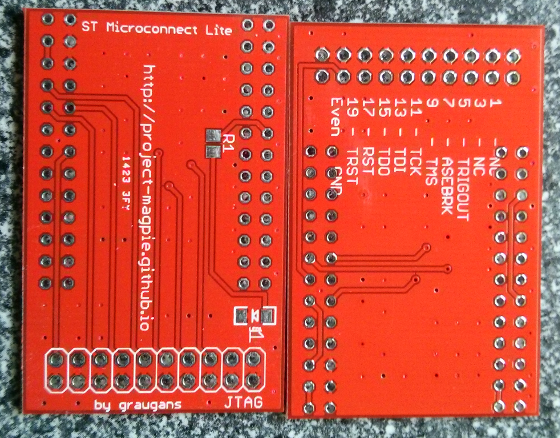
After assembly of the PCB the JTAG adapter have to be connected to the STB. If you are unsure about the pinning you can easily check if Pin-2 is connected to GND with a multimeter.

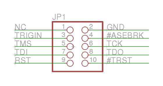
A more detailed version reconstructed in eagle.
Anyway, most hardware is useless without software. To use the JTAG Adapter the ST40 Micro Toolset is needed. You can grab your version of the ST40 Micro Toolset at the STM ftp server. As usual I decided to take the linux version (R5.1.0). I have tested with Ubuntu 12.04. Maybe the 32bit compatibility libs have to be installed if you are running a 64bit distro. You also need the ST Micro Connection Package R1.6.0.. After Installation the folder structure should look like this:
$ tree -L 1 /opt/STM/
/opt/STM/
├── ST40R5.1.0
└── STMCR1.6.0
To be able to execute the binaries some modifications to the PATH and LD_LIBRARY_PATH variable have to be made.
export LD_LIBRARY_PATH=/opt/STM/STMCR1.6.0/lib:/opt/STM/ST40R5.1.0/lib
export PATH=/opt/STM/ST40R5.1.0/bin:/opt/STM/STMCR1.6.0/bin:$PATH
Now you sould be able to execute the following command
$ sh4xrun
usage: /opt/STM/ST40R5.1.0/bin/sh4xrun [-c command] [-d directory] [-e filename] [-f] [-g gdbpath] [-h] [-i filename] [-t     target] [-u gdbname] [-v] [-x filename] [-A command] [-B command] [-C option] [-D] [-T timeout] [-V] [-a|--] [arguments]
  -a arguments  target program arguments
  -c command    connection command (default is sh4tp)
  -d directory  directory in which to search for command files
  -e filename   executable file to load
  -f            (ignored)
  -g gdbpath    specify path to GDB
  -h            display help
  -i filename   command script file to source
  -t target     target specification
  -u gdbname    specify name of GDB
  -v            verbose
  -x filename   use filename instead of .shgdbinit
  -A command    execute command after running program
  -B command    execute command before running program
  -C option     connection command option
  -D            debug (very verbose)
  -T timeout    maximum time for executing on target
  -V            version string
With this command a executable can be uploaded and executed right on the box. But what kind of executable is worthwhile to be uploaded? On Avi+ Forum they use a tool called flasher which is upload to the box. I prefer to use a self compiled version of u-boot. And honestly I did not managed to compile a flasher for the sti7111.
Compilation of U-Boot
Before we can compile the u-boot boot loader we have to get the source
$ git clone git://git.stlinux.com/stm/u-boot.git
$ cd u-boot/
$ git checkout -b stmicro-1.3.1 origin/stmicro-1.3.1
I decided to use stmicro-1.3.1 branch It sounds familiar and I was unable to build the stmicro branch. To compile the source I used a toolchain I’ve created with to meta-stlinux layer and yocto.
$ source /opt/poky/1.5.1/environment-setup-sh4-poky-linux
$ export CROSS_COMPILE=sh4-poky-linux-
$ unset LDFLAGS
$ make hdk7111_config
$ vim ./cpu/sh/config.mk
# remove option  -m4-nofpu
After a successful compilation you have a file called u-boot. This can be uploaded by executing:
sh4xrun -c sh4tp -t STMCLT1000_A:sat7111:st40,debug=2 -e /data/src/u-boot/u-boot
On a working serial console connected to the STB you should see something like this:
Board: STx7111-HDK  [29-bit mode]


U-Boot 1.3.1-dirty (Jun 15 2014 - 18:23:57) - stm23-2011-12-08

DRAM:  256 MiB
NOR:     8 MiB
NAND:  Bad block table found at page 262080, version 0x01
Bad block table found at page 262016, version 0x01
nand_read_bbt: Bad block at 0x04400000
nand_read_bbt: Bad block at 0x06580000
nand_read_bbt: Bad block at 0x065a0000
nand_read_bbt: Bad block at 0x0e580000
nand_read_bbt: Bad block at 0x0e5a0000
nand_read_bbt: Bad block at 0x10c00000
nand_read_bbt: Bad block at 0x10c20000
nand_read_bbt: Bad block at 0x16580000
nand_read_bbt: Bad block at 0x165a0000
nand_read_bbt: Bad block at 0x18c00000
nand_read_bbt: Bad block at 0x18c20000
nand_read_bbt: Bad block at 0x1dc40000
nand_read_bbt: Bad block at 0x1dc60000
nand_read_bbt: Bad block at 0x1e580000
nand_read_bbt: Bad block at 0x1e5a0000
512 MiB
SPI:  ERROR: Unknown SPI Device detected, status = 0xff
*** Warning - bad CRC, using default environment

In:    serial
Out:   serial
Err:   serial
It looks like the SPI NOR Flash is not supported by this version of u-boot. So work is to do….
EDID Mission Accomplished
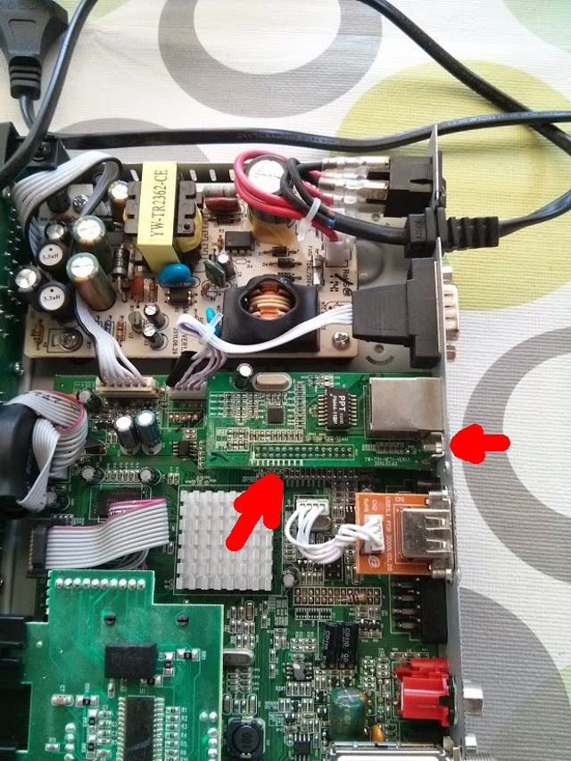
After my HDMI EDID analisys I decided getting more in touch with the hardware. I tried to trace the loose ends and checked where the onboard EEPROM is located. The next step was disabling the EEPROM and connecting the STB I2C Bus to the HDMI side.As in my previous post expected the missing SOT-23 parts near the HDMI output form a level shifter which convert the 3.3V I2C STB level to the 5V level of the HDMI side an vice versa.
A detailed description of such an level shifter is described in an application note from Phillips/NXP.
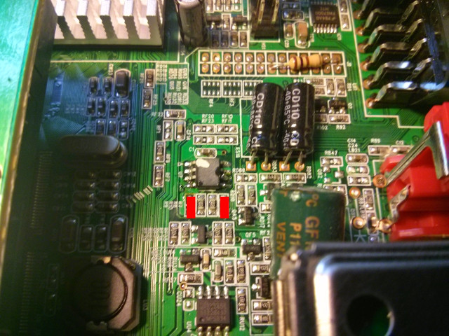
I started with the trace of the EEPROM. I finally found the EEPROM.
There are two serial resistors between I2C SCL and I2C SDA. Which can be more or less easily removed.
After soldering my very first sot-23 transistor which made me feeling like my soldering iron is too huge for decent jobs. I cursed myself for not taking the box to work where we do have a more professional equipement at least when it comes to soldering irons.
The result looks ugly but seems to work.
As Transistor I’ve chosen some N-Channel Field Effect Transistor. Anything like a 2N7002 or a BSS138 should do the job.
For me the final result was a working EDID readout of the HDMI monitor’s EDID EEPROM. And the first time the STB took the correct HDMI-CEC address. I had not been able to check levels and edges of the 5V signal and the ultimate HDMI-CEC test also have to wait some time. Because my test lab HDMI monitor have no HDMI-CEC support.
Pursue HDMI EDID Bugs
Today I tried to track down the EDID (“Extended display identification data”) bug on my STi7111 (Golden Media 990CR ) spark box. EDID is needed to detect the display attached to the set-top box. On the newer STi7105 based boxes this works quite good. But on the STi7111 based spark boxes there is a hardware issue.
During EDID query the frame-buffer driver prints out the following warning message:
stmfb: first EDID byte (255) is corrupt, attempting to fix..
stmfb: Invalid extension header checksum block0
stmfb: first EDID byte (255) is corrupt, attempting to fix..
stmfb: Invalid extension header checksum block0
stmfb: first EDID byte (255) is corrupt, attempting to fix..
stmfb: Invalid extension header checksum block0
stmfb: first EDID byte (255) is corrupt, attempting to fix..
stmfb: Invalid extension header checksum block0
stmfb: EDID Read Error, setup safe EDID
stmfb: Setting Safe EDID
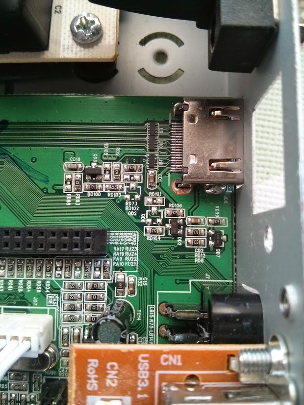
So I decided to take a look at the hardware and do some test. Because EDID is needed for a working HDMI-CEC set-up. The EDID information is stored inside an EEPROM on the Television/Montor. The EEPROM is accessed by the STB via an I2C bus.
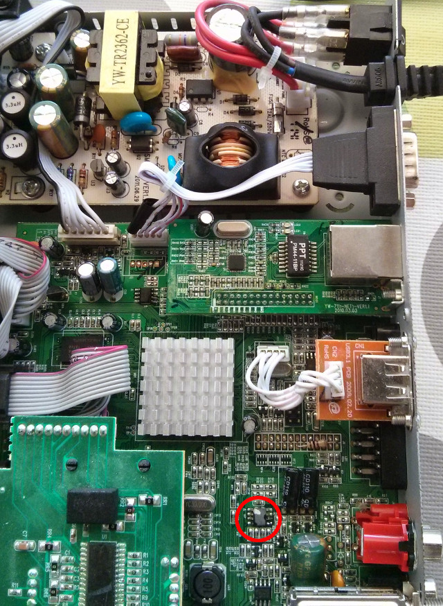
The result looks a little bit chaotic isn’t it?
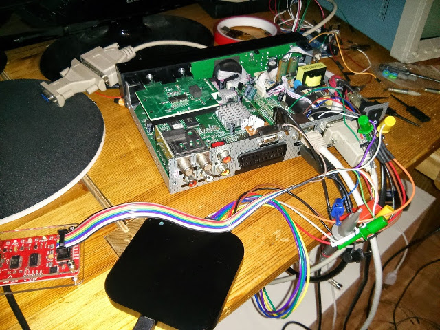
The image shows the set-top box, a salea logic16 logic analyser and a DP Bus Pirate. The salea logic analyser is to listen to I2C communication between the various loose ends. Before we can access the HDMI connector and the I2C EDID data lines we have to remove the Ethernet board. This is achieved by removing just one screw and lifting the complete Ethernet board.
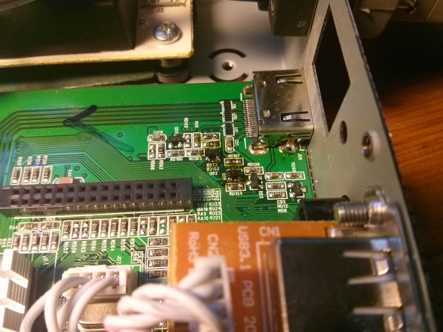
After removing the Ethernet board it looks like this:
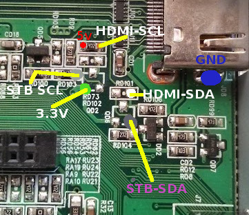
For debugging purposes I soldered some wires to the related components. There are two types of I2C bus involved. The one from HDMI which is a 5V type and the one from the STB which is at a 3.3V level. So the not applied components seems to form a level shifter. If I attach an HDMI monitor to the STB I can see transfers from STB to an EEPROM on the board which response with 0xFF in all bytes. But no communication over HDMI. Because the loose ends are not connected.
With an attached bus pirate to the HDMI I2C bus I can readout the EDID information from the attached monitor.
HiZ>m
1. HiZ
2. 1-WIRE
3. UART
4. I2C
5. SPI
6. 2WIRE
7. 3WIRE
8. KEYB
9. LCD
10. PIC
11. DIO
x. exit(without change)

(1)>4
I2C mode:
 1. Software
 2. Hardware

(1)>1
Set speed:
 1. ~5KHz
 2. ~50KHz
 3. ~100KHz
 4. ~400KHz
The i2c sequence to read data from the EEPROM have to define a start address where we want to read from:
I2C>[0xa0 0]
I2C START BIT
WRITE: 0xA0 ACK
WRITE: 0x00 ACK
I2C STOP BIT
With this we start from address 0.
So now lets read 128 byte of EDID data:
I2C>[0xa1 r:128]
I2C START BIT
WRITE: 0xA1 ACK
READ: 0x00  ACK 0xFF  ACK 0xFF  ACK 0xFF  ACK 0xFF  ACK 0xFF  ACK 0xFF  ACK 0x00  ACK 0x04  ACK 0x72  ACK 0x30  ACK 0x02  ACK 0x01  ACK 0x00  ACK 0x00  ACK 0x00  ACK 0x08  ACK 0x15  ACK 0x01  ACK 0x03      ACK
 0x80  ACK 0x33  ACK 0x1D  ACK 0x78  ACK 0x0A  ACK 0x90  ACK 0x85  ACK 0xA3  ACK 0x58  ACK 0x53  ACK 0x9F  ACK 0x26  ACK 0x0F  ACK 0x50  ACK 0x54  ACK 0xBF  ACK 0x6F  ACK 0x00  ACK 0x71  ACK 0x4F  ACK     0x81
  ACK 0xC0  ACK 0xD1  ACK 0xC0  ACK 0xB3  ACK 0x00  ACK 0x81  ACK 0x80  ACK 0x01  ACK 0x01  ACK 0x01  ACK 0x01  ACK 0x01  ACK 0x01  ACK 0x02  ACK 0x3A  ACK 0x80  ACK 0x18  ACK 0x71  ACK 0x38  ACK 0x2D      ACK
 0x40  ACK 0x58  ACK 0x2C  ACK 0x45  ACK 0x00  ACK 0xFD  ACK 0x1E  ACK 0x11  ACK 0x00  ACK 0x00  ACK 0x18  ACK 0x01  ACK 0x1D  ACK 0x00  ACK 0x72  ACK 0x51  ACK 0xD0  ACK 0x1E  ACK 0x20  ACK 0x6E  ACK     0x28
  ACK 0x55  ACK 0x00  ACK 0xFD  ACK 0x1E  ACK 0x11  ACK 0x00  ACK 0x00  ACK 0x1E  ACK 0x00  ACK 0x00  ACK 0x00  ACK 0xFD  ACK 0x00  ACK 0x38  ACK 0x4C  ACK 0x1E  ACK 0x4B  ACK 0x0F  ACK 0x00  ACK 0x0A      ACK
 0x20  ACK 0x20  ACK 0x20  ACK 0x20  ACK 0x20  ACK 0x20  ACK 0x00  ACK 0x00  ACK 0x00  ACK 0xFC  ACK 0x00  ACK 0x4D  ACK 0x32  ACK 0x33  ACK 0x30  ACK 0x48  ACK 0x44  ACK 0x4C  ACK 0x0A  ACK 0x20  ACK     0x20
  ACK 0x20  ACK 0x20  ACK 0x20  ACK 0x01  ACK 0x56
NACK
I2C STOP BIT
We do not need any pull-ups power set-up for the Bus Pirate because the bus is already pulled high by the STB. And due to the fact that I2C only pulls level to low we need no adjustment for 3.3V and 5V.
With some editor regular-expression magic we can form a python snippet to create a binary EDID file we can analyse later.
import struct
edid_txt = [ '0x00', '0xFF', '0xFF', '0xFF', '0xFF', '0xFF', '0xFF', '0x00',
             '0x04', '0x72', '0x30', '0x02', '0x01', '0x00', '0x00', '0x00',
             '0x08', '0x15', '0x01', '0x03', '0x80', '0x33', '0x1D', '0x78',
             '0x0A', '0x90', '0x85', '0xA3', '0x58', '0x53', '0x9F', '0x26',
             '0x0F', '0x50', '0x54', '0xBF', '0x6F', '0x00', '0x71', '0x4F',
             '0x81', '0xC0', '0xD1', '0xC0', '0xB3', '0x00', '0x81', '0x80',
             '0x01', '0x01', '0x01', '0x01', '0x01', '0x01', '0x02', '0x3A',
             '0x80', '0x18', '0x71', '0x38', '0x2D', '0x40', '0x58', '0x2C',
             '0x45', '0x00', '0xFD', '0x1E', '0x11', '0x00', '0x00', '0x18',
             '0x01', '0x1D', '0x00', '0x72', '0x51', '0xD0', '0x1E', '0x20',
             '0x6E', '0x28', '0x55', '0x00', '0xFD', '0x1E', '0x11', '0x00',
             '0x00', '0x1E', '0x00', '0x00', '0x00', '0xFD', '0x00', '0x38',
             '0x4C', '0x1E', '0x4B', '0x0F', '0x00', '0x0A', '0x20', '0x20',
             '0x20', '0x20', '0x20', '0x20', '0x00', '0x00', '0x00', '0xFC',
             '0x00', '0x4D', '0x32', '0x33', '0x30', '0x48', '0x44', '0x4C',
             '0x0A', '0x20', '0x20', '0x20', '0x20', '0x20', '0x01', '0x56' ]

f = open('edid.bin', 'w')

for i in edid_txt:
    bin = int(i,16)
    f.write(struct.pack('B',bin))

f.close()
For EDID analysis I’ve used to tool “read-edid” which contains a tool called “edid-decode”.
$ edid-decode edid.bin
Extracted contents:
header:          00 ff ff ff ff ff ff 00
serial number:   04 72 30 02 01 00 00 00 08 15
version:         01 03
basic params:    80 33 1d 78 0a
chroma info:     90 85 a3 58 53 9f 26 0f 50 54
established:     bf 6f 00
standard:        71 4f 81 c0 d1 c0 b3 00 81 80 01 01 01 01 01 01
descriptor 1:    02 3a 80 18 71 38 2d 40 58 2c 45 00 fd 1e 11 00 00 18
descriptor 2:    01 1d 00 72 51 d0 1e 20 6e 28 55 00 fd 1e 11 00 00 1e
descriptor 3:    00 00 00 fd 00 38 4c 1e 4b 0f 00 0a 20 20 20 20 20 20
descriptor 4:    00 00 00 fc 00 4d 32 33 30 48 44 4c 0a 20 20 20 20 20
extensions:      01
checksum:        56

Manufacturer: ACR Model 230 Serial Number 1
Made week 8 of 2011
EDID version: 1.3
Digital display
Maximum image size: 51 cm x 29 cm
Gamma: 2.20
Supported color formats: RGB 4:4:4, YCrCb 4:2:2
First detailed timing is preferred timing
Established timings supported:
  720x400@70Hz
  640x480@60Hz
  640x480@67Hz
  640x480@72Hz
  640x480@75Hz
  800x600@56Hz
  800x600@60Hz
  800x600@75Hz
  832x624@75Hz
  1024x768@60Hz
  1024x768@70Hz
  1024x768@75Hz
  1280x1024@75Hz
Standard timings supported:
  1152x864@75Hz
  1280x768@60Hz
  1920x1152@60Hz
  1680x1050@60Hz
  1280x1024@60Hz
Detailed mode: Clock 148.500 MHz, 509 mm x 286 mm
               1920 2008 2052 2200 hborder 0
               1080 1084 1089 1125 vborder 0
               -hsync -vsync
Detailed mode: Clock 74.250 MHz, 509 mm x 286 mm
               1280 1390 1430 1650 hborder 0
                720  725  730  750 vborder 0
               +hsync +vsync
Monitor ranges: 56-76HZ vertical, 30-75kHz horizontal, max dotclock 150MHz
Monitor name: M230HDL
     Has 1 extension blocks
Checksum: 0x56
The result looks quite good isn’t it? One of the next step would be to connect the loose ends. Or trying to write useful information to the on board eeprom.